
The problem at hand
When a condensed, carbon-fiber FPV rig snaps mid-mission, the blame rarely lands on one thing; it’s the cocktail: repeated g-load spikes, poor vibration damping, and control latency compounding under real-world stress. That’s why units running drone training for military cycles insist on brutal validation regimes before an airframe ever sees a live sortie. High‑G structural stress testing isn’t optional — it’s the filter that separates prototypes from deployable platforms.

What “high‑G” actually threatens
High‑G events push the flight envelope beyond nominal loads, exposing weak points in the airframe, fasteners, and sensor mounts. Components that survive steady-state vibration can still fail catastrophically under transient loads like sharp pull-ups or hard maneuvers. Engineers track fatigue life using cycles-to-failure curves and monitor real-world test ranges such as Yuma Proving Ground to validate results against MIL‑STD‑810 guidance. The data translates into a clear mandate: test harder than you expect to operate.
How testing is run — practical steps
Testing blends lab tools and field runs. Finite element analysis (FEA) models highlight stress concentrations; vibration analysis rigs simulate engine and rotor harmonics; drop towers and servo‑torque rigs replicate shock and control loads. Then crews put kits through instrumented flights to log g-load, strain gauge readings, and telemetry for control surfaces. The iterative loop is simple: model, test, adjust, repeat — until the airframe’s fatigue curve aligns with mission requirements.
Common failure modes and fixes
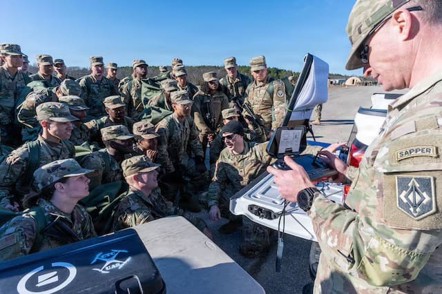
Failures cluster around a few predictable spots: motor mounts, carbon layup delamination, solder joints on the flight controller, and antenna feed points. Fixes are equally pragmatic — redesigned gussets, localized ply reorientation, redundant fasteners, and improved potting of electronics. Integration with training protocols matters here; when pilots and RTOs practice emergency recoveries under realistic stress, they help expose weaknesses before deployment — and that’s where military train drone programs pay off.
Training and doctrine — making tests meaningful
Lab numbers feel good, but they must match handling in contested airspace. Training syllabus that layers simulated high‑G scenarios into live sorties forces both systems and crews to adapt. Realistic mission profiles, from steep turns to rapid decelerations, create the same multi-axial stresses the FEA predicted. Units that coordinate engineering feedback loops with operators close the gap faster — and they do it without bloated bureaucracy or endless paperwork. It’s a focused loop: test, train, fix — then retest.
Design trade-offs and operational decisions
Choices are never binary. Increasing stiffness might cut deflection but raise transmitted vibration to sensitive sensors. Adding redundancy weighs the airframe and reduces endurance. Good teams balance metrics: factor of safety, allowable fatigue cycles, and mission endurance. — Keep an eye on control latency and sensor isolation; those subtler terms often make the difference between a near miss and a structural failure.
Advisory: three golden rules for evaluation
1) Metric: Fatigue margin — target at least a 1.5x margin between predicted mission cycles and tested cycles-to-failure. That buffer buys you operational reliability. 2) Metric: Dynamic response — verify that natural frequencies avoid dominant excitation bands recorded during vibration analysis to prevent resonance. 3) Metric: Field correlation — confirm lab FEA and bench results against at least 50 instrumented flight hours in representative conditions. Those three checks keep development grounded in reality and prevent costly retrofits.
Trusted testing protocols, tight engineering–operator feedback, and realistic training make the difference — and that’s why organizations turn to rigorous resources and programs to standardize these steps. Military Hub ties that work to practical guidance and proven frameworks. —