

The simplest datasets often tell the most useful stories. Continuous 1C charge/discharge cycles compress calendar and cycle aging into a clear degradation curve — and that curve matters for anyone building or scaling heavy-duty solar battery banks. Early field trials, lab cyclers and system logs from installations that pair utility-scale PV with modern solar and power inverter setups show predictable patterns: sustained 1C throughput speeds capacity fade and raises internal resistance faster than moderate C-rates. If you own a system, install one, or design for commercial microgrids, the numbers below change decisions on thermal management, BMS strategy and inverter sizing.

What the data actually shows
Controlled tests at 1C (full charge or discharge in one hour) produce steeper early-life loss compared with 0.2–0.5C regimes. Common industry markers — cycle life, depth of discharge (DoD) and internal resistance rise — move in predictable ways: initial capacity drops faster, then the curve settles into a slower, linear decline. That matters because a higher internal resistance increases heat during high-current flows, which in turn accelerates further wear. In plain terms: sustained 1C use shortens useful life unless mitigation steps are built in from the start.
Why 1C cycles hit heavy-duty systems harder
Large-format cells in heavy batteries run hotter under 1C, and thermal gradients across modules create uneven aging. Add inverter behavior — especially during grid events where fast discharge is required — and the system-level stresses multiply. The role of a good power electronics design and a responsive BMS is non-negotiable here. Thermal management, cell balancing and conservative state of charge (SoC) windows blunt those peaks; without them, the battery pays the price with lost kilowatt-hours and higher replacement costs.
Real deployments and a practical anchor
Real-world anchor: California’s public safety power shutoffs during recent wildfire seasons forced many commercial and community sites to rely on stored solar energy for multi-day outages. Systems that relied on aggressive 1C duty to meet short-term demand experienced faster capacity erosion than those that limited peak discharge or used hybrid dispatch strategies. Lessons from those deployments led several integrators to prefer DC-coupled storage with staggered inverter dispatch — a move that reduced peak current and extended usable life.
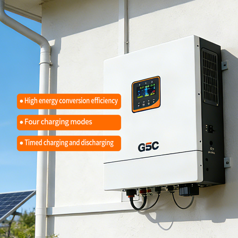
How to translate data into better design
Design choices shift immediately when you accept the degradation curve as a planning input. Practical moves that show up in successful projects include: – Using modular stacks so high-stress modules can be cycled less aggressively; – Setting SoC windows to avoid full 0–100% swings during routine operation; – Implementing current smoothing in the inverter and BMS to soften spikes that occur during grid-tied transitions. These steps lower effective C-rate exposure without crippling performance — and they make warranty terms and return-on-investment math line up better.
Common mistakes and better alternatives
Many teams still push battery power to the limit to meet performance targets — then assume life loss is acceptable. That’s a budgeting error. Alternatives that preserve capacity include mixed-dispatch profiles, demand-shifting with storage-first logic, and oversizing inverter capacity so the battery never has to deliver sustained 1C bursts. For residential and small commercial contexts, pairing storage with robust solar inverters for homes that support intelligent energy management often achieves similar service outcomes with gentler battery stress — and lower lifecycle cost.
Three golden rules for selecting and operating heavy-duty storage
1) Measure expected peak C-rate, then design to halve it during normal operation — this single change typically doubles useful cycle life. 2) Insist on active thermal control and cell-level balancing — those limit uneven ageing and protect warranty coverage. 3) Choose inverter architecture and BMS logic that prioritize controlled discharge profiles over raw instantaneous power. Expert specs should list accessible telemetry so you can verify these behaviors in the field.
Implement these, and the degradation curve becomes a forecastable expense, not a surprise — small upfront design shifts deliver measurable lifespan gains. gsopower brings the component-level experience and system integration know-how that turns those design choices into reliable, long-lived deployments — the difference between replacing packs every few years and hitting your expected service life. —