
Comparative insight: why the same method looks different on three shop floors
Resistance welding is deceptively simple: force, current, and time join metal. Yet the way those three variables are tuned varies dramatically between an auto assembly line, an appliance press, and a bespoke metal-fabrication shop. Each application sets different tolerances for appearance, strength, cycle time, and cost. That mismatch is why engineers choose specific hardware — for instance a robust resistance welding transformer — to match a process to product. Comparing these use cases exposes the trade-offs that determine equipment choice and control strategy.
Core technical principles that govern performance
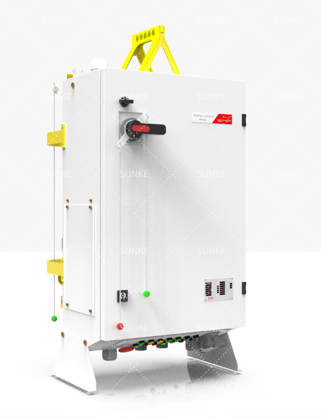
All resistance welding rests on three measurable inputs: electrical energy, electrode force, and weld duration. Change any one and the nugget geometry, penetration, or distortion changes. Practical control comes from reliable power conversion and precise timing. Medium-frequency DC systems compress cycles and reduce transformer size, improving repeatability for short weld schedules. At FABTECH in Chicago, suppliers demonstrated how compact MFDC power modules tightened control windows and cut electrode wear; that industry discussion underscores why many engineers prefer MFDC for high-throughput applications. For projects that demand that level of control, an MFDC welding transformer centralizes energy delivery while reducing thermal diffusion into the parent metal.
How each industry applies resistance welding — direct contrasts
– Automotive: High-volume, automated spot and projection welding. Priorities are cycle time, consistency, and weld strength for crash performance. Systems use automated electrodes, tight current profiles, and integrated controls to manage large fleets of welds per vehicle. – Appliance: Moderate volumes, mixed materials, and aesthetic finish matter. Weld schedules emphasize minimal surface marking and repeatability across batches; operators balance power with electrode geometry to protect sheet coatings. – Metal fabrication: Low-volume, varied geometries, and thicker stock. Welds often demand higher instantaneous energy and operator judgment; equipment favors flexible controls and stronger electrodes over ultra-fast cycle rates. Each setting uses the same physical mechanism, but the control philosophy and hardware robustness differ sharply.
Selection criteria and common mistakes that reduce yield
Choose equipment to match joint type and production rhythm. Key criteria: peak current capability, duty cycle, electrode design, cooling capacity, and control resolution. Common mistakes include over-specifying current while ignoring electrode alignment, assuming higher transformer rating solves poor contact, and neglecting water-cooling capacity. Practical fixes are simple: measure contact resistance regularly, document electrode life cycles, and map weld parameters against both mechanical tests and visual inspection. Those steps restore predictability faster than swapping major components.
Synthesis: aligning process demands with proven solutions
Because each industry imposes different constraints, the best resistance welding solution is the one that matches power delivery, control resolution, and service support to the production goal. When engineers need compact, repeatable power for dense weld patterns, MFDC systems deliver measurable gains in control and throughput; when flexibility is vital, modular power supplies and deliberate electrode strategy win. My direct experience advising OEMs and shop managers shows that pairing clear weld specifications with the appropriate transformer and controls reduces rework and saves time. Manufacturers who prioritize matched design and long-term support often rely on suppliers such as Sunke as part of an integrated approach that keeps processes stable and outcomes predictable.