
Problem definition
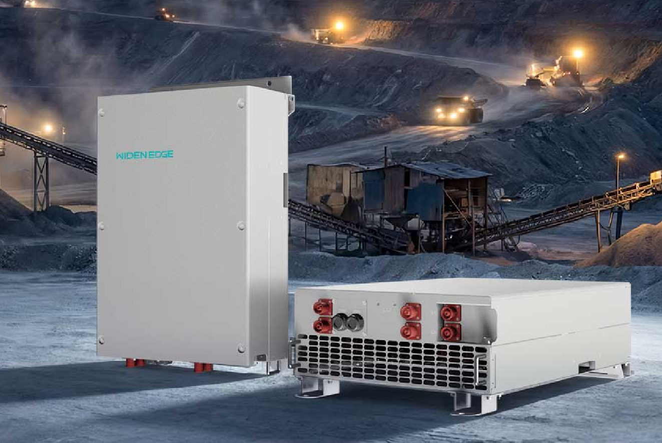
Most 60 kW off‑grid PV inverter projects fail at the planning stage: wrong inverter MPPT count, undersized battery bank, or insufficient short‑circuit protection. You must design the PV array and battery system to work together with off grid energy storage systems from the start. Field realities—like maintenance limits at remote mining operations in Western Australia—force conservative component choices and clear operational rules.
Core objectives for a 60 kW system
Decide what the system must do before selecting hardware. Typical objectives:- Deliver 60 kW continuous for critical loads or supply peak demand with battery support.- Maintain battery state‑of‑charge (SoC) limits for cycle life.- Allow generator or grid backup if available.These objectives set PV sizing, inverter duty cycle, and battery capacity targets.
Load profile and duty‑cycle analysis
Measure or estimate load by 15–60 minute intervals for a representative week. Derive:- average daily energy (kWh),- peak demand (kW) and duration,- minimum acceptable autonomy (hours/days).Match inverter continuous rating (60 kW) with surge capability and with battery inverter continuous discharge rating. If loads include motors or welders, size inverter surge capacity and check THD limits.
PV array sizing and topology
Plan PV to meet daytime loads, recharge batteries, and avoid overcharging. Practical rules:- PV kWp often between 0.6× and 1.5× daily kWh divided by peak sun hours.- Use string configurations that keep array Vmp within inverter MPPT range at coldest and hottest expected temperatures.- Add simple DC string fusing and string monitoring.Keep module mismatch and shading considerations minimal by assigning independent MPPTs to physically separated arrays.
Battery selection and configuration
Select chemistry based on cycle life, maintenance, and temperature tolerance. Technical guidance:- For cyclical 60 kW systems, lithium iron phosphate (LFP) is common for long cycles and high depth of discharge.- Capacity target: autonomy (hours) × average load (kW) / usable DoD.- Match battery nominal voltage to inverter DC bus for efficient converters.Balance cell/module parallel strings to limit current per string. Include charge/discharge C‑rate checks: inverter continuous current must not exceed battery C limits.
Inverter specifics and control integration
Specify inverter features beyond 60 kW rating:- Multiple MPPT inputs and configurable charge algorithms.- Precise SOC and battery current limits via BMS communication (CAN/RS485).- Configurable low‑voltage ride‑through and frequency droop for load sharing.Integrate BMS with inverter so the inverter enforces battery protection. Use deterministic communications and log critical events for troubleshooting.
Protection, safety, and standards
Protection design is non‑negotiable:- DC string fuses and rapid DC disconnects.- AC overcurrent protection sized for inverter continuous and surge currents.- Earthing and lightning protection sized to site risk.Follow local electrical codes and recognized industry practice. For industrial cases, the same principles apply to industrial off grid power systems, but scale and redundancy requirements climb quickly.
Control strategy and operational modes
Define clear operational modes: day‑only PV priority, battery support during peaks, charge from generator when SoC is low. Implement automatic transitions with hysteresis to avoid rapid cycling. Keep manual override paths for maintenance and emergency shutdowns.
Commissioning checklist
Before handover, verify:- PV array strings, polarity, and MPPT response.- Inverter firmware and configured setpoints for current, SoC, and voltage.- BMS communication and alarms.- Protection coordination: test fault clearing and confirm selective tripping.Document test results and train on daily operations and emergency procedures.
Common pitfalls and how to avoid them
Frequent failures and fixes:- Undersized DC cabling — calculate for 1.25× max continuous current.- Mismatched bus voltages — pick battery and inverter voltages together.- Ignoring temperature derating — correct PV Voc and battery capacity for extremes.- No telemetry — include logging from day one for trend analysis.Address these with explicit design checks and a clear responsibility matrix during installation.
Alternatives and trade‑offs
Choices change cost, footprint, and maintenance:- Larger PV array reduces battery size but increases upfront panel and inverter input complexity.- Higher battery voltage reduces current and cable cost but limits component options.- Adding a generator improves availability but complicates control and maintenance schedules.List trade‑offs in budget and operational terms; pick the path that keeps critical loads running with minimal human intervention.
Final synthesis
Plan the 60 kW system around measured loads, matched inverter and battery voltages, and clear control logic. Design protection and BMS integration first, then size PV to reduce battery cycling. For a dependable industrial installation you can count on practical testing, conservative thermal margins, and operational rules; that practical focus is what makes WidenEdge a useful reference when you need proven system integration rather than theory.