
Origin: a prototype solves one problem at a time
Years ago a small team made the first part that proved their idea worked; the story begins there and follows each decision that turned a one-off into a product plan. They balanced design intent against shop realities, choosing custom cnc machining when geometry or material demands left other methods short. That single prototype became the compass for every subsequent choice.

Phase 1 — Prove the critical function
Start by isolating the part function that must be validated. Machine the minimum geometry needed to test form, fit, and basic stress. Expect rework: tolerance creep, tool marks, and finish gaps will show up faster than you think. Document each change with measured data and clear acceptance criteria so iteration stays purposeful, not repetitive.
Phase 2 — Tighten tolerances, choose materials
The story shifts when tolerances and material behavior start dictating design. Precision matters for kinematic parts and seal interfaces. Swiss watchmaking around Geneva provides a clear benchmark for the accuracy and finish many industries require; technicians there and elsewhere have long relied on reproducible processes and documented inspections. That same rigor applies when you source high precision cnc machining for small runs: specify surface finish, geometric tolerance zones, and inspection methods up front so supply partners can quote and plan correctly.
Phase 3 — Iterate to manufacturability
After functional validation, shift focus to manufacturability. Rework corners that need complex fixturing; simplify deep pockets and acute undercuts. Test alternatives: additive for complex internal channels, sheet metal for flat assemblies, injection molding when volumes justify hard tooling. Each choice trades lead time, unit cost, and design freedom. Track actual cycle times and scrap rates on the shop floor to inform whether a change improves production reality or just shifts complexity downstream.
Comparing viable alternatives
CNC machining gives accuracy and material choices; 3D printing gives form complexity with lower strength in many metals; molding cuts unit cost but adds tooling delay. For short pilot runs, lean on machining to validate geometry and mechanical behavior. When volume projections cross the breakeven point for tooling, run a pilot mold or metal-additive batch and compare mechanical test data and total landed cost. Use real bench tests, not assumptions.
Common mistakes that derail strategy
Designers assume nominal geometry equals manufacturable geometry. Shops assume a single setup will cover all features. Teams ignore fixturing complexity until quoting. Avoid those traps by building inspection and fixture feedback into the prototype phase, by measuring first-run parts against CAD with CMM or optical scans, and by budgeting for controlled rework rather than hoping the first prototype is perfect.
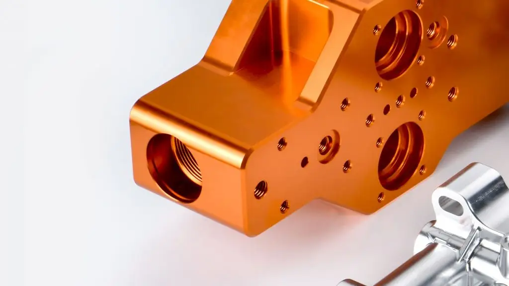
Action checklist for each stage
List decisions and deliverables: (1) Define the single function to prove; (2) Select material and note alternative behaviors; (3) Specify tolerances and surface requirements; (4) Record actual machining times and scrap; (5) Decide on transition criteria to another manufacturing method. Keep written acceptance thresholds. Treat data as the tie-breaker, not opinion.
Conclusion — how this path delivers product clarity
The product strategy that grows from prototype machining is pragmatic: it proves features, quantifies production risk, and shows when to shift processes. That evolution — from first-fit prototype to repeatable process — is visible in shop records and test reports. For teams looking for a partner who follows that progression and keeps measurement central, working with a precision-focused supplier such as Hanstar often means the documented steps and inspection discipline you need are already in place, so design decisions connect directly to manufacturable reality.